Discussion of Optically Clear Adhesives
Introduction
Optically Clear Adhesive (OCA) improves the brightness and contrast of a touch screen. It allows a clearer and more vivid user experience. With the level of integration today's mobile computing devices play in our daily lives, OCA helps enrich the user's interaction and engagement with their touch screen devices.
Thin-film-transistor liquid crystal display (TFT-LCD) technology replaced traditional cathode ray tube (CRT) as the primary leader of display technology approximately ten years ago. One of the key benefits of a TFT-LCD display is that screen size is very flexible, from small screens of 1" to very large screens of 100". This innovation created numerous new opportunities for screen design, impacting dimensions and end-use applications.
Multi-point projective capacitive touch panel technology was similarly developed about ten years ago. This technology characterizes the touch panel's precise positioning capability and very fast response times.
The combination of TFT-LCD display and multi-point projective capacity touch panel technology has been a revolutionary product introduction, specifically for mobile computing devices, taking the phone from a simple communication tool to allowing the ability to quickly and easily use handheld technology for hundreds of different applications.
One inherent problem with touch panel display technology is that light transmittance decays as incremental materials are stacked upon one another, degrading picture and screen quality. This is where Boyd's expertise in OCA brings the ideal solution. Optically Clear Adhesives help to solve transmittance problems by improving brightness and contrast in the touchscreen, providing the high quality image consumers demand.

Snell’s Law
To understand how light is transmitted through OCA, the basic principles and theory of Snell’s Law are important.
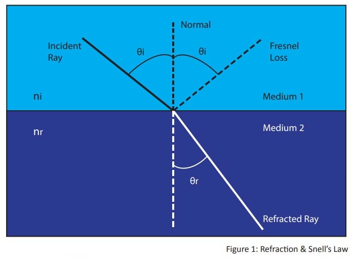
As shown in Figure 1, when a light ray is incident on a boundary of two mediums, for example air and plastic, the light will be refracted when it crosses the boundary.
Refraction occurs because the light changes velocity when it travels across two mediums. The index of refraction, n, is the ratio of the speed of light in vacuum to the speed of light in a specific medium.
- θi = incident angle in medium 1
- θr = refraction angle in medium 2
- ni = refractive index of medium 1
- nr = refractive index of medium 2
- Snell’s Law = ni sin θi = nr sin θr
Fresnel Loss
Fresnel loss, as shown in Figure 2, is a transmission loss due to reflection at a boundary when the mediums have different refractive indexes.


How OCA Works
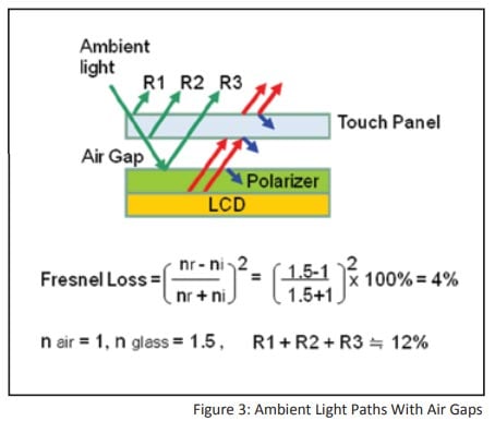
Figure 3 shows how ambient light travels through touch panel and TFT-LCD displays without OCA.
There are air gaps between the two components. This air gap and the difference in refractive index is what causes a loss of transmittance.
The refractive index of air is 1 while the refractive index of a touch panel and polarizer is about 1.5. The reflection at each boundary is 4%, based on the Fresnel Loss calculation. There are three boundaries in this case, therefore 12% ambient light is reflected to the user's eyes.
Ambient light reflection is considered "noise" to the user's eyes because it reduces the contrast of the screen. The contrast is 12% worse with this air gap and refractive index difference.
Additionally, 4% light from the display will be reflected out of the user's view at each boundary. The brightness is 12% incrementally worse with this air gap.
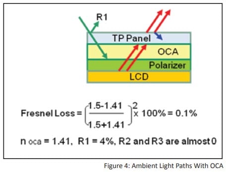
Figure 4 shows how ambient light travels through a touch panel and TFT-LCD display with OCA.
The refractive index of OCA is between 1,4 to 1.5, which is very close to that of the touch panel or polarizer. Based on a Fresnel Loss calculation, the ambient light reflection is almost zero at the boundaries of OCA. There is ambient light reflection of only 4% at the surface of the touch panel.
The light from the LCD travels through OCA with almost no loss. The only light loss is 4% at the surface of the touch panel.
OCA improves screen contrast by 8% and screen brightness by 8%.
OCA Segments
There are two segments in the OCA materials industry. One is a sheet-type of solution, the other is liquid. Sheet form is called OCA and liquid form is Optically Clear Resin (OCR) or Liquid OCA (LOCA).
Touch screen makers dispense OCR or LOCA on a touch panel in a special fishbone pattern and then laminate to the TFT-LCD display. After lamination, a UV curing process is applied. The benefits of OCR or LOCA include no custom OCA converting requirements and reduced inventory requirements as there is no need for specific touch screen size and dimensional designs driving diversity in stock. The disadvantages of OCR or LOCA include liquid leakage and uneven curing defects.
Touch screen makers laminate the sheet form of OCA on a touch panel then laminate the touch panel with OCA on a TFT-LCD display. The benefits of the sheet form of OCA include mature materials in the market, decreasing material costs due to technological improvements and higher manufacturing yields. The disadvantages of the sheet form of OCA include leading edge converting manufacturing technology requirements, high cleanliness environment requirements and inventory of specific sizes and dimension to meet the needs of various phone models.
Boyd is well experienced with the equipment and environments required to produce tight tolerance precision converted components with high cleanliness requirements — ideal for converting custom-designed OCA solutions.
OCA Converting Cleanliness Requirements
To meet the needs of ever-increasing visual experience improvements, the resolution of TFT-LCD displays continually climbs, like VGA (640 x 480), WXGA (1280 x 768), Full HD (1920 x 1080) and 4K2K (3840 x 2160). When resolution increases, display pixel density increases, meaning pixel size becomes smaller and smaller. A retina display has more than 300 pixels per inch (PPI) for smartphones or more than 260 PPI for tablets.
Smaller pixel size means more defined, critical and tighter particle contamination specifications. For example, no particle the size of 0,02 mm² or greater is allowed in a 10" retina display area.
Maintaining cleanliness is one of the most challenging tasks in OCA converting processes, especially with the ever-increasing contaminant specifications. In addition to requiring ultra clean room environments (Class 1000 or better), machine setup, line layout, temperature and humidity control, operating methods and dress code will directly impact the cleanliness of components to be assembled in a device display.
OCA Applications
The design engineer must consider all aspects of excitation sources present for a typical operating device, understand how the device's structural response influences these sources, and make wise design and component choices early in the design cycle to help avoid undesirable noise and vibration characteristics. Often design and manufacturing trade-offs must be made to meet both performance and cost targets.
Elimination of all noise and vibration problems at the source level is often impossible to achieve for a variety of reasons: precision components are cost prohibitive, it is difficult to control manufacturing variation and tolerance stack-up, or simply that these factors were not taken into consideration early in the design cycle when changes were possible. Therefore, some form of modification to the structural dynamics of the device is necessary, and the most attractive option is often some form of converted add-on countermeasure that can isolate the structural transmission of vibration, block or capture the radiated airborne noise, or damp the unwanted resonant amplification. Understanding the basic nature of a specific NVH condition is the starting point in knowing which types of treatments are most appropriate to consider.
The more detailed and nuanced activity then involves the optimization of these control devices as each must be tailored for the specifics of the structure at the frequency and temperature range of the application. Achieving this while also meeting other product requirements (like RoHS compliance, flammability ratings, and cost constraints, etc.) is the challenge facing today's product designer. In future White Papers, we will take a deeper dive into the optimization process of various converted noise and vibration solutions provided by Boyd.
Conclusion
The structure of a smartphone touch screen. One piece of OCA adheres the glass screen to the touch panel. The other piece of OCA adheres the LCM to the touch module.
With Class 100 to Class 100.000 cleanroom facilities, advanced rotary converting technologies and disciplined operations teams, Boyd offers OCA die-cut solutions for market segments and applications including:
- Smartphones (< 5”)
- Phablets (5 – 8”)
- e-Books (6 – 9”)
- Tablets (8 – 13”)
For your OCA challenges, engage Boyd early in the design cycle to ensure that the most functional and cost effective designs are in place prior to emergent situations at product launch.
Use Boyd’s years of experience and engineering support in concert with your engineering and technical expertise to ensure your OCA challenges are solved in a cost effective, leading edge way.
Have questions? We’re ready to help!
