
Calculating the Thermal Resistance of a Heat Exchanger
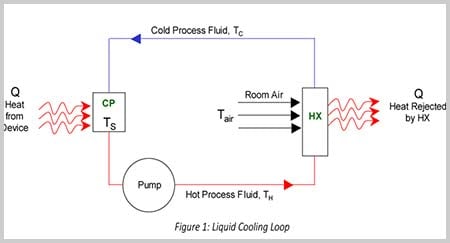
Figure 1 shows a typical liquid cooling loop, consisting of a cold plate (CP), pump, and heat exchanger (HX) connected by hoses or tubing. Since the components are part of a system, it is important to select them together to ensure proper component sizing for your application. Manufacturers typically provide performance data for cold plates and heat exchangers individually, with cold plate performance in thermal resistance and heat exchanger performance in thermal capacity. So how do you select the optimal heat exchanger and cold plate for the complete system? It is easier than you might think, since the equations needed to determine the right cold plate and heat exchanger combination reduce to a very simple format:
![]()
To arrive at this equation, the first step is to calculate the cold plate thermal resistance, θCP, which is defined as the difference between the maximum required surface temperature, TS, MAX, and fluid exit temperature, TH, divided by a heat load, Q, evenly distributed over the entire cold plate surface:
![]()
Similarly, heat exchanger thermal capacity, CHX, which is defined as the heat load, Q, divided by the temperature differential between two incoming fluids, TH -TAIR, is described by the following equation:
![]()
Thermal capacity is also equal to the inverse of thermal resistance:
![]()
Assuming no heat gains from the pump or heat losses through connecting hoses or tubing between the cold plate and heat exchanger (since these are usually minor), equations (2), (3) and (4) can be combined into one simple equation:
![]()
Hot process fluid temperature TH has dropped out of the formula because liquid temperature has been removed from the equation, we do not have to calculate flow rates and heat capacities of the liquid. We are just left with the desired surface temperature of the cold plate, as well as the temperature of ambient air cooling the heat exchanger, and the performance is fully characterized by the thermal resistances of the cold plate and heat exchanger. Therefore, we no longer have to analyze the individual components of the system. Instead we determine the thermal resistance of the entire system. Note that the effect of flow is not excluded from the results because it is already incorporated within thermal resistance values.
A customer wants to use a CP12 a 12" (30,48 cm) cold plate (plate side), to remove 1200 W of heat from a 12"x5" (30,48 cm x 12,7 cm) electronic device. The coolant is 1 gpm (3,79 LPM) of water and room temperature is 20°C. The customer wants the smallest heat exchanger that will remove 1200 W of heat generated by this device, while maintaining a maximum surface temperature of 80°C.
Step 1: First we determine system thermal resistance, θSYSTEM:
![]()
Step 2: Any combination of cold plates and heat exchangers that provide a thermal resistance less than or equal to the total system requirement will work. In other words:
![]()
Step 3: Table 1 shows the resistance and flow rates of the CP12 cold plate and two different heat exchanger/fan combinations:
| Flow Rate (gpm) | θCP (CP12) (°C/W) | θHX (6110 w/Kona fan) (°C/W) | θHX (6210 w/Marin Fan) (°C/W) |
| 0,5 | 0,01 | 0,05 | 0,02 |
| 1 | 0,01 | 0,05 | 0,02 |
| 1,5 | 0,01 | 0,04 | 0,02 |
| 1,5 | 0,01 | 0,04 | 0,02 |
| 2 | 0,01 | 0,04 | 0,02 |
Table 1 shows that the CP12/6110 combination satisfies the 0,05 °C/W condition at 2 gpm (0,01 +0,04 = 0.048.
By looking at the system as a whole, we start to see trade offs between the components, including how flow rate can impact heat exchanger selection. At low flow rates, cold plate thermal resistance increases. This requires a larger heat exchanger with more thermal capacity, and therefore lower thermal resistance. At higher flow rates, it is possible to use a smaller heat exchanger.
Liquid-to-air heat exchangers and cold plates are often combined in a fluid circuit, so it is important to understand how to select the components simultaneously to optimize your system's performance. With accurate specifications and a simplified equation, selecting the components in your liquid cooling loop can be relatively straightforward. In addition, by selecting components from the same thermal vendor, you use components that are tested in a similar manner and are more likely to work well as a system.
Cabinet Cooling Thermal Calculations
How to Calculate the Required Thermal Resistance for a Cabinet or Enclosure
![]()
Heat exchanger manufacturers usually present thermal performance data as a function of heat load and incoming air and water flow rates. This works well for applications where the heat exchanger is used to cool water with air, as you can simply plug in your heat load, air temperature, and liquid temperature to determine if it offers sufficient thermal performance.
Cabinet cooling applications use the heat exchanger in the opposite configuration - cold water flows in the liquid circuit and warm air from the cabinet is cooled as it passes across heat exchanger fins. In cabinet cooling applications, you usually need to know the temperature of air as it enters the cabinet, and the maximum temperature that air in the cabinet will reach. Neither of these can be read directly from heat exchanger performance curves.
The usual way to calculate the temperature change of air is to use the mass flow rate calculation.
This can be time-consuming and prone to error.
To avoid these calculations, Boyd developed charts to quickly estimate temperature rise in common heat transfer media at various heat loads. Graphs are available for air, water, oil, and 30/70 ethylene glycol-water (EGW). To calculate temperature change, simply select the appropriate graph, look up your flow rate and heat load, and read off the temperature change. In our technical library under thermal reference you can view a pdf or our temperature change graphs.
When used in conjunction with product performance curves, these offer a quick and simple way of calculating the temperature of cold air entering the cabinet, and maximum air temperature in the cabinet.
Example Cabinet Cooling Calculation
You are evaluating a 6310 heat exchanger with an Ostro fan for cooling an electronics cabinet. The water entering the heat exchanger is at 20°C and a flow rate of 1 gpm. The heat load, Q, is 2400W.
What is the temperature of cooled air entering the cabinet (i.e. the temperature of air leaving the heat exchanger) and what is maximum temperature in the cabinet (i.e. the temperature of warm air entering the heat exchanger)?
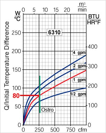
First check the performance curve of 6310 in the catalog. You will see that with a 1gpm water flow and the Ostro fan which supplies approximately 250 cfm, its performance is 80W/°C.
Since we know that Q is 2400W and Q/ITD is 80°C/W, we can calculate Initial Temperature Difference (ITD).
ITD = 2400W ÷ 80°C/W = 30°C
We also know that incoming water temperature is 20°C. We can therefore calculate incoming air temperature:
The incoming air temperature = 20°C + 30°C = 50°C.
To determine outgoing temperature of the air, we use the ‘Air Flow’ chart using parameters 250 CFM and 2400 W.
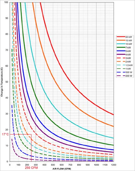
We find the change in temperature is approximately 17°C. The outgoing air temperature is 50°C – 17°C = 33°C.
We know that this heat exchanger with the Ostro fan will cool air to 33°C, and the hottest temperature air in the cabinet will reach is 50°C.
To determine the outgoing temperature of water we use the ‘Water Flow’ chart.

At 1 gpm and 2400 W, this shows that the change in temperature is approximately 9°C. Therefore, the outgoing water temperature is 20°C + 9°C = 29°C.
Graphs for air, water, oil, and EGW are available in downloadable PDF format. These are helpful for sizing heat exchangers and cold plates and are also useful in a variety of other temperature change calculations.


